
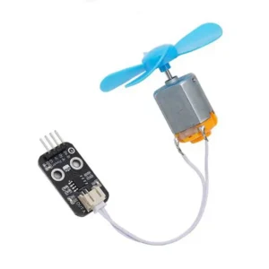
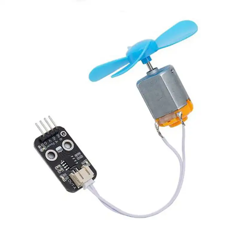
L9110 Motor Driver Module with Fan
The L9110S Motor Driver Module is a compact and easy-to-use motor control board designed for driving small DC motors in robotics, Arduino projects, and embedded control applications. Based on the L9110S motor driver IC, the module provides two motor control channels, making it suitable for small robot cars, motorized models, and other DIY electronic projects.
The L9110S features two TTL/CMOS-compatible input channels and offers strong anti-interference performance. Each output channel can provide approximately 750–800 mA of continuous drive current under suitable operating conditions, with peak current reaching approximately 1.5–2.0 A according to the supplied specifications. The IC operates at a typical 5V supply voltage, allowing convenient integration into many microcontroller-based systems.
The module controls motor direction through two input signals, INA and INB. By changing the logic levels of these inputs, users can control forward rotation, reverse rotation, and stopping. Applying a PWM signal to a control input also enables motor speed adjustment, making the module suitable for applications that require flexible motor control.
The driver module is compatible with popular development platforms such as Arduino, 51-series microcontrollers, STM32, and ESP32, the L9110S Motor Driver Module provides a practical solution for educational robotics, DIY projects, and small motor control systems.
Key Features
-
Based on the L9110S motor driver IC
-
Dual-channel DC motor drive capability
-
TTL/CMOS-compatible control inputs
-
Supports forward and reverse motor rotation
-
Supports motor stopping and PWM speed control
-
Typical operating voltage: 5V
-
Continuous output current: approximately 750–800 mA per channel, subject to operating conditions
-
Peak output current: approximately 1.5–2.0 A, subject to datasheet limits
-
Compact design for easy integration
-
Suitable for Arduino, STM32, ESP32, and other microcontrollers
Operating Principle
The l9110 motor driver direction is controlled by the logic levels applied to the INA and INB input pins.
| INA | INB | Motor Operation |
|---|---|---|
| LOW | LOW | Stop |
| HIGH | HIGH | Stop |
| LOW | HIGH | Rotate in one direction |
| HIGH | LOW | Rotate in the opposite direction |
The physical forward and reverse directions depend on the motor wiring.
For speed control, a PWM signal can be applied to an appropriate input to adjust the l9110 motor driver’s effective drive power. Ensure the control signals and supply voltage remain within the device’s electrical ratings.
Applications
-
Arduino robot cars
-
Small DC motor control
-
Educational robotics projects
-
DIY electronic toys
-
Motorized models
-
Embedded control systems
-
Smart car projects
-
STEM learning and prototyping
Technical Specifications
| Parameter | Specification |
|---|---|
| Product Name | L9110S Motor Driver Module |
| Driver IC | L9110S |
| Motor Channels | 2 |
| Logic Compatibility | TTL/CMOS |
| Typical Operating Voltage | 5V |
| Continuous Output Current | Approx. 750–800 mA per channel, under suitable conditions |
| Peak Output Current | Approx. 1.5–2.0 A, subject to device limits |
| Control Inputs | INA, INB |
| Motor Control | Forward, reverse, stop, PWM speed control |
| Compatible Platforms | Arduino, 51, STM32, ESP32 |
| Applications | Robotics, small DC motors, DIY electronics |
Note: Actual current capability depends on the IC’s thermal conditions, power supply, and board design. Peak current is not a continuous operating rating. Verify the manufacturer’s datasheet before selecting the module for a specific motor.
Packing List:
L9110 Driver Module with fan, exactly as the picture.


Reviews
There are no reviews yet.